In my last post, I explained the basics of the Ladder Diagram programming language.
In this one, I'll show you how to write Ladder Diagram logic in Studio 5000 Logix Designer.
Write Ladder Diagram Logic
In Studio 5000 Logix Designer, application code is written in routines. By default, a MainRoutine is created for you when you create a project.
To open the MainRoutine, expand the MainProgram folder in the Controller Organizer and double-click on MainRoutine.
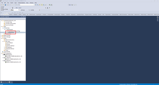
The Ladder Diagram editor opens, and you can see that the routine contains a single rung.
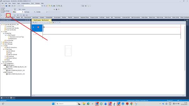
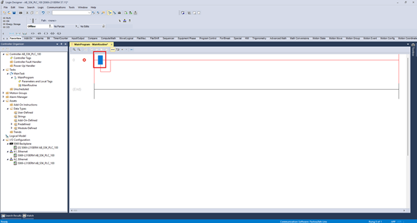
You can add Program Elements to a rung by dragging them from the Program Elements toolbar and dropping them on the rung. When you drag an element from the Program Elements Toolbar, grey dots appear on the rung. These dots indicate where on the rung a program element can be placed.
When you hover over a dot, it becomes green. A green dot indicates where on the rung the program element will be added.
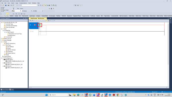
When you release the mouse, the Program Element is added to the rung.
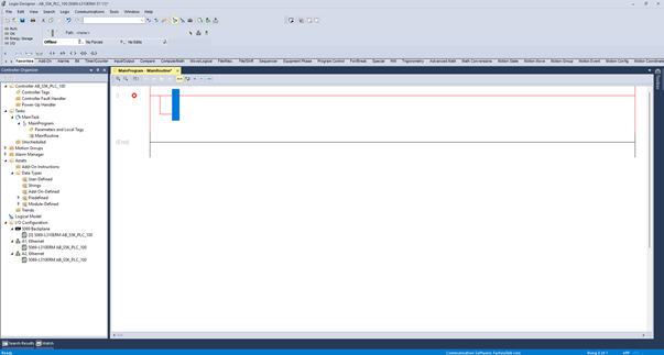
You can also add elements by selecting a part of the rung and then clicking on the Program Element to add to the rung. For example, you can select the opening of the branch.
Then click on an XIC instruction to add it inside the branch.
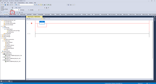
When you add an instruction to a rung, it's added with a question mark over it. This question mark indicates that a tag hasn't been associated with the instruction yet.
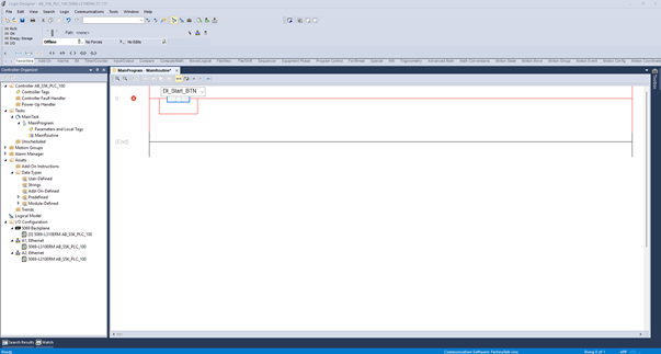
To associate a tag with an instruction, click on the question mark and begin typing the name of the tag. As you type, Studio 5000 Logix Designer will try to autocomplete the name based on the tags that are available. When the correct tag is showing, press enter to select the tag.
The tag needs to already be declared in the Tag Editor before you can associate it with an instruction this way.
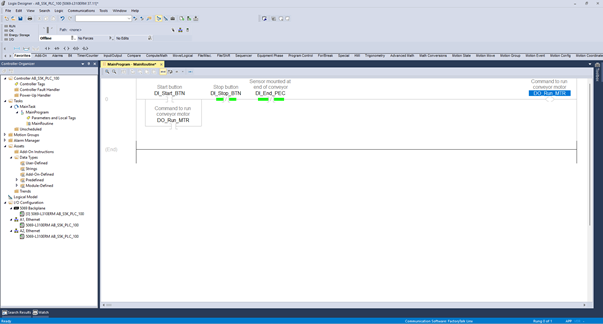
You can repeat this process to add all of the required instructions to the rung.
If you need to control multiple outputs, you can do this in a number of different ways, including:
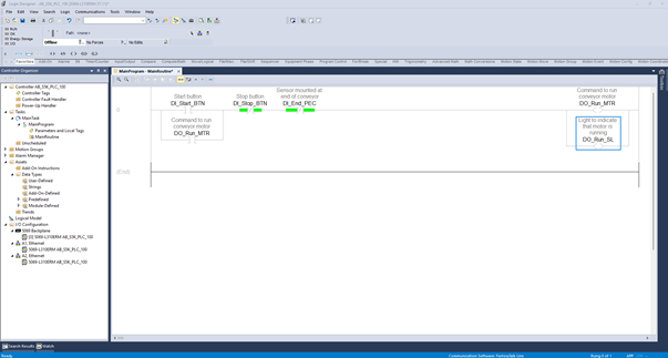
Placing two outputs in series on the rung.
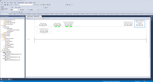
Placing two outputs in parallel on the rung using a branch.
Placing the logic to control the light on a dedicated rung.
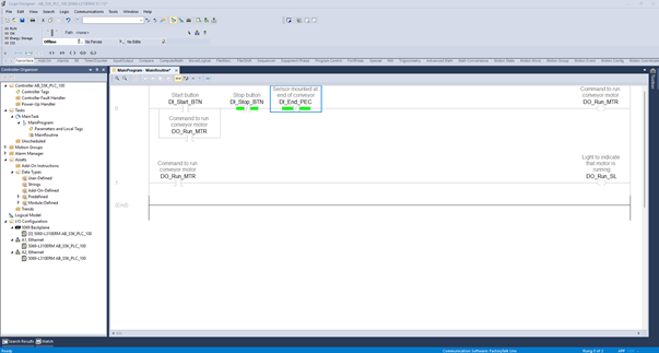
All of this code effectively executes the same in the PLC, so the way you program the logic comes down to personal taste and company guidelines. If you're not sure which approach to pick, placing the logic on a dedicated rung is usually the easiest to read and troubleshoot, since it keeps the light's logic separate from the motor's logic.
Wrap Up
In this post, I showed you how to write a simple Ladder Diagram in Studio 5000 Logix Designer.
Learn PLC Programming in your browser
Learn PLC programming by building projects in your browser - no hardware or software required.
Then €29.97/month · Cancel any time