In a previous post, I introduced the Ladder Diagram programming language. That post covered the most common Ladder Diagram instructions, how instructions can be combined to create complex Boolean logic, and touched briefly on the concept of a seal-in circuit. If you missed it, you can find that post here.
In this post, I'm going to circle back to talk about seal-in circuits in more detail because they are such an important part of PLC programming. By the end of this post, you will know:
- What a seal-in circuit is and why it's used in PLC programming,
- The components that make up a seal-in circuit,
- How seal-in circuits work, and
- Practical applications of seal-in circuits
Let's get started by talking about what a seal-in circuit is.
What is a Seal-In Circuit in PLC Programming?
In PLC programming, a seal-in circuit is a design pattern that is used to maintain an output after the input that energized the output is removed.
That definition might sound a bit confusing, so let's look at a practical application.
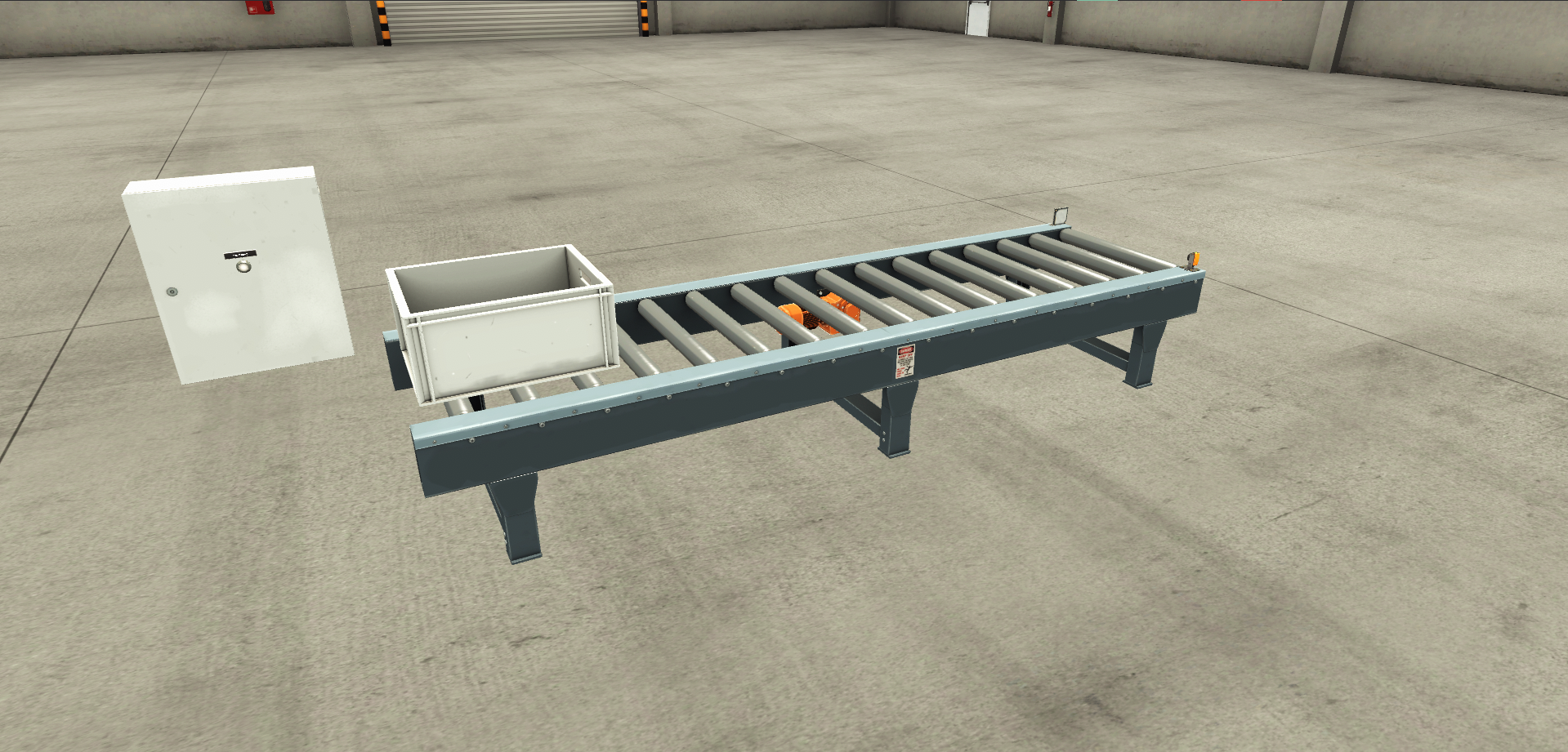
In a warehouse, you may have a conveyor that transports totes from one side of the warehouse to the other. To start the conveyor, an operator has to press a start button. Once he has pressed the start button, the conveyor continues to run even after the start button is released.
This is an example of a seal-in circuit because the output (which runs the conveyor motor) is maintained after the input (which is the start button) is removed.
Now that we know what a seal-in circuit is, let's look at the components that make up a seal-in circuit.
Seal-In Circuit Components
A seal-in circuit is made up of four key components:
- Permissives,
- Interlocks,
- Output, and
- Seal-In Contact
Let's look at teach one of those components in detail.
Permissives
.png)
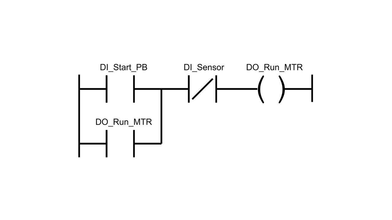
Permissives are the inputs that energize the outputs. These input conditions must be True for the output to be energized, but don't need to remain True for the output to remain energized.
In the example above, the start button is a permissive.
Interlocks
.png)
Interlocks are conditions which unseal a seal-in circuit. If an interlock condition is not True, then the output is switched off.
In the example above, an interlock condition might be the input for a sensor at the end of the conveyor. When this sensor is triggered, the conveyor must stop running to avoid the tote falling on the floor and potentially damaging products.
In general, most seal-in circuits will use a stop button as an interlock so that a process can be stopped in a controlled way. This stop button should always be programmed and wired as normally closed (NC). This means if a wire breaks or comes loose, the circuit will stop rather than continue running. This is a critical safety feature
Output
.png)
The output is the part of the seal-in circuit that is energized when permissives and interlocks are True.
In the example above, the output to run the conveyor motor is the output of the seal-in circuit.
Seal-In Contact
.png)
The seal-in contact is the part of the seal-in circuit that seals in the output. This is a condition that is placed in parallel to the permissives and references the output.
The seal-in contact creates an alternative path to achieve logical continuity on the rung and keeps the output energized even when the permissives are no longer present.
Now that we know the components that make up a seal-in circuit, let's look at how a seal-in circuit works.
Seal-In Circuits Operation
Here's a quick explanation of how a seal-in circuit actually works in a PLC.
Step 1: Initial State
Initially, the permissives are False and the output is not energized.
Step 2: Permissives Become True
.png)
To energize the output, the operator presses the start button. This makes the permissives True and the output is energized since the interlocks are also True.
Step 3: Output is Sealed In
.png)
Once the output is energized, the seal-in contact seals in the status of the output.
Step 4: Permissives Become False
.png)
Since the output is energized, the operator releases the start button and the permissive conditions become False.
Because the status of the output is sealed in, the output remains energized and the conveyor continues to run.
Step 5: Interlocks Become False
Eventually, the tote reaches the end of the conveyor and triggers the sensor. This makes the interlock conditions become False and unseals the output.
The output is de-energized and the conveyor stops running.
Wrap Up
In this post, I explained in detail what a seal-in circuit is and how a seal-in circuit works in PLC programming. This is one of the most common design patterns that you will encounter so its important to understand.
If you want to build a seal-in circuit in Studio 5000 Logix Designer, use the link below to start your 30 day free trial of a Controls Engineering Academy membership. Your membership includes access to all of our courses on programming Allen Bradley Logix 5000 PLCs using Studio 5000 Logix Designer and our interactive simulations that let you practice programming in your browser without any software or hardware.
You can also maintain an output using latch instructions like Output Latch and Output Unlatch. In my next post, I will explain the difference between these two approaches and why seal-in circuits are preferred for applications with moving parts like conveyors, pumps, and fans.
Learn PLC Programming in your browser
Learn PLC programming by building projects in your browser - no hardware or software required.
Then €29.97/month · Cancel any time