In my last post, I covered tag concepts in Studio 5000 Logix Designer. Now that you know what tags are, I'll walk you through the basics of Ladder Diagram, the programming language you'll use to write logic for your PLC.
In this post, you'll learn:
- How to read Ladder Diagram code,
- How the most common Ladder Diagram instructions work, and
- What a seal-in circuit is.
Let's get started.
Ladder Diagram
Ladder Diagram is the most popular programming language for PLCs. It's a high-level graphical programming language that's easy to write and troubleshoot.
In Ladder Diagram, each line of code is called a rung because it resembles a physical rung on a ladder.
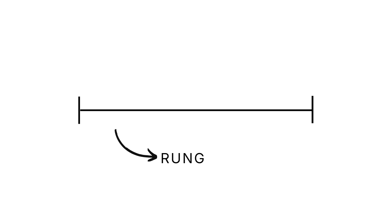
You program Ladder Diagram logic by adding instructions to the rung and linking the instructions to tags.
There are two basic categories of instructions: input instructions and output instructions.
Output Instructions
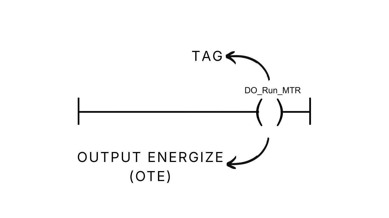
Output instructions write a value to a tag and are positioned on the right of the rung.
Here, I've added an Output Energize instruction to the rung and linked it to an output that runs a motor. You may also hear Output Energize abbreviated to OTE.
Let's look at how this is executed in the PLC.
The vertical bar on the left of the rung is called the power rail.
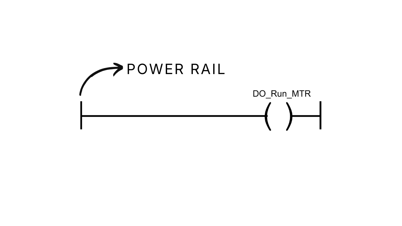
When there's a continuous path from the power rail to an output instruction, the instruction evaluates to true. Another way to say this is that the rung-in condition for the instruction is true.
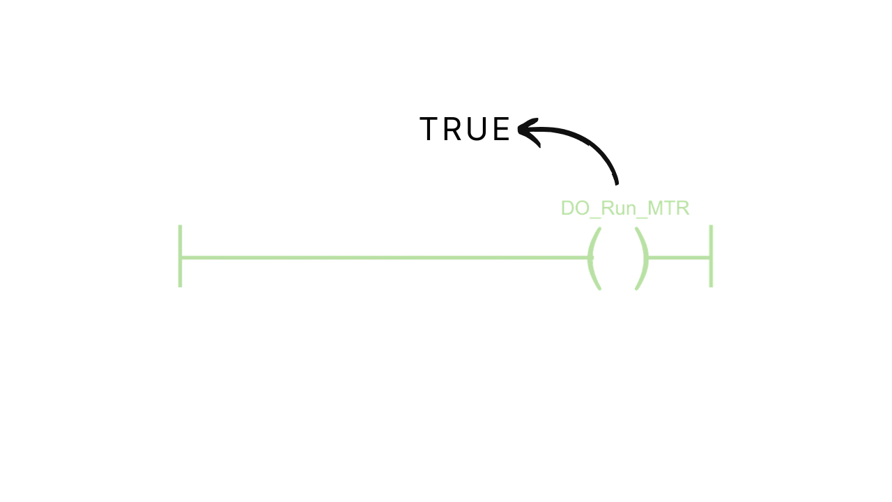
An Output Energize instruction writes the value true to its linked tag when it evaluates to true. If it doesn't evaluate to true, it writes the value false to its linked tag.
In this example, there's always a continuous path from the power rail to the output instruction. So every time this code is executed, the value true is written to the tag DO_Run_MTR, and the motor runs.
Input Instructions
You can use input instructions to control outputs.
Unlike output instructions, input instructions read the value of a tag and evaluate to true or false based on the value of the tag.
Here, I've added an Examine If Closed, or XIC, instruction to the rung and linked it to an input from a start button.
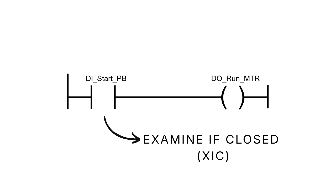
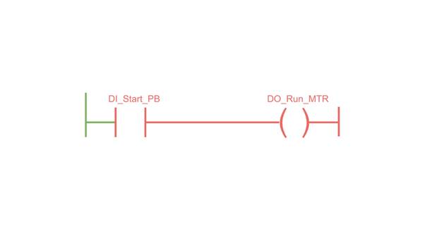
When the tag DI_Start_BTN is True, the instruction evaluates to true. This creates a continuous path from the power rail to the output instruction, and the motor runs.
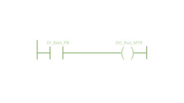
When the start button isn't pressed, the instruction evaluates to false. Since there isn't a continuous path to the output instruction, the motor doesn't run.
You can describe this logic as:
If the start button is pressed, then run the motor.
AND Logic
You can also create complex logic on a rung by combining instructions.
If you place instructions in series, you create AND logic, where all of the conditions in a set must be true to turn on an output.
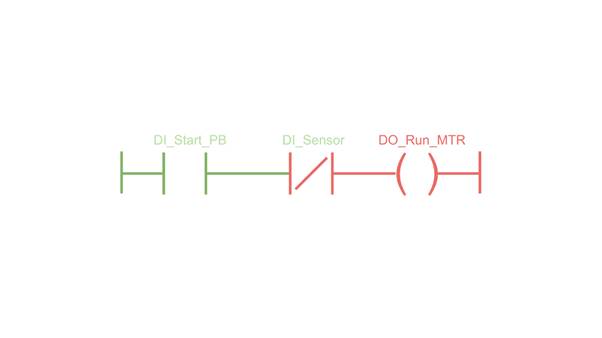
Here, I've added an Examine If Open, or XIO, instruction to the rung. This instruction is the exact opposite of an XIC instruction: it evaluates to True if its linked tag is False, and to False otherwise.
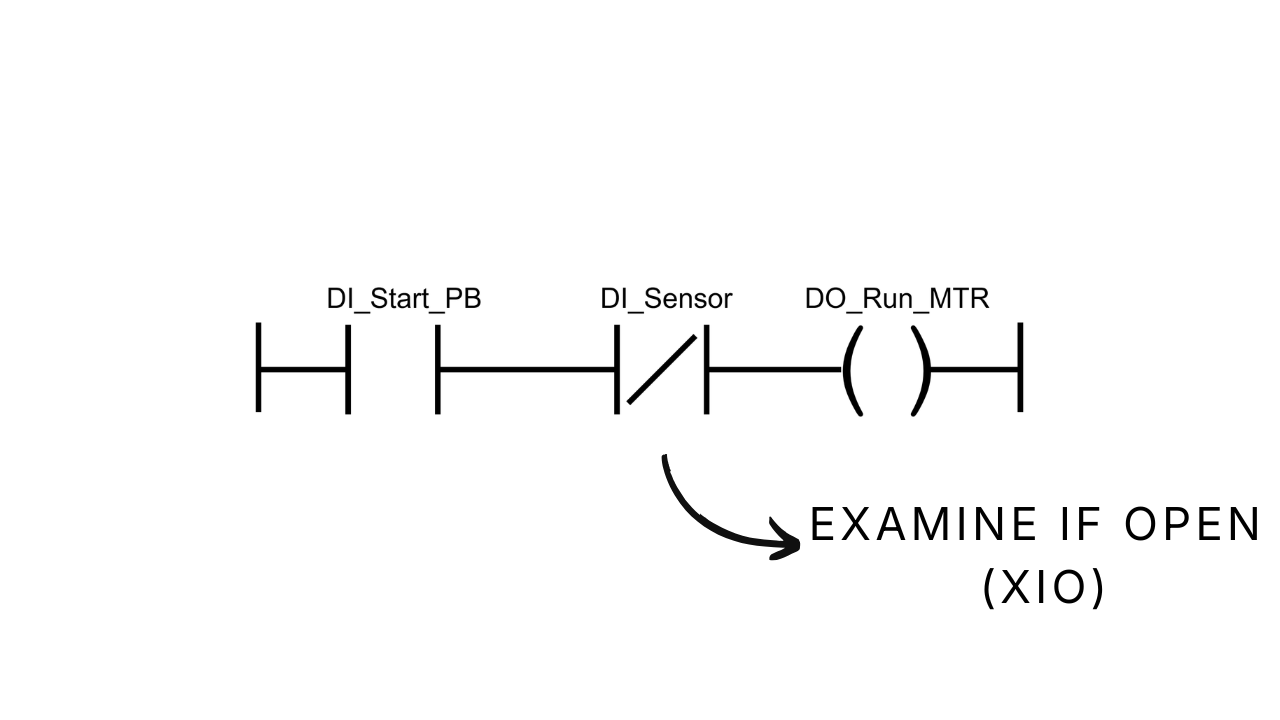
Now the motor runs if the Start button is pressed AND the sensor isn't triggered.
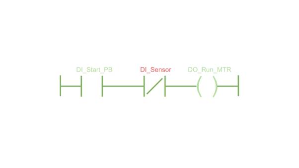
It won't run if the Start button isn't pressed or the sensor is triggered.
OR Logic
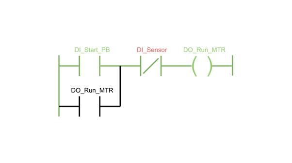
You can also create OR logic by placing instructions in parallel on a rung.
You use branches to place instructions in parallel. A branch creates an alternative path to achieve logical continuity on a rung.
.png)
Now, the motor runs when the Start button is pressed and the sensor isn't triggered.
Once the Start button is released, the motor continues to run because the motor is running.
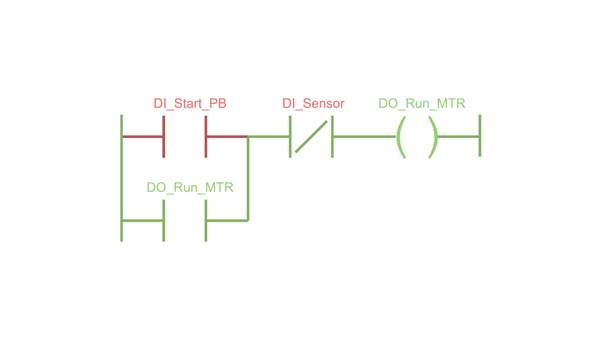
The motor continues to run until the sensor is triggered.
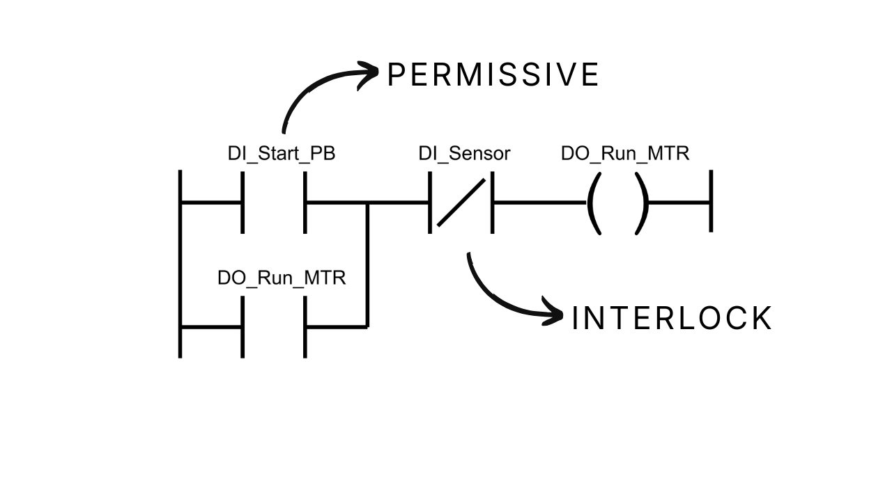
Seal-In Circuits
This is a common design pattern in PLC programming called a seal-in circuit. It's called a seal-in circuit because the output is sealed in by the branch.
The main components of a seal-in circuit are permissives and interlocks.
Permissives are conditions that have to be true for a process to start, but don't have to remain true for the process to run. In this case, the Start button is a permissive.
Interlocks are conditions that have to be true for a process to run. If an interlock condition is missing, the process stops. In this example, the sensor is an interlock condition because the motor won't run if the sensor is triggered.
In Allen-Bradley Logix 5000 PLCs, seal-in circuits are non-retentive. This means that if the PLC loses power, the output isn't true when the PLC is powered up again. That's really important for logic that controls motors, since you don't want things to start moving unexpectedly.
Seal-in circuits are non-retentive because the Output Energize instruction has pre-scan logic that's executed before the logic is scanned for the first time. This logic sets the instruction to False and unseals the output.
Wrap Up
In this post, I covered the basics of Ladder Diagram: how rungs work, the difference between input and output instructions, how to build AND and OR logic, and the fundamentals of seal-in circuits.
If you'd like a deeper look at seal-in circuits, including the seal-in contact itself and how a stop button fits in as an interlock, check out my other post on Seal-In Circuit Concepts.
Learn PLC Programming in your browser
Learn PLC programming by building projects in your browser - no hardware or software required.
Then €29.97/month · Cancel any time