In my last post, I showed you how to create a project in Studio 5000 Logix Designer. Before diving into programming, it helps to understand how tags work, since you'll use them to read and write data throughout a project.
In this post, I'll explain what tags are in Studio 5000 Logix Designer. By the end, you'll understand:
- Tags,
- Data Types,
- Memory allocation,
- Attributes, and
- Parameters
Let's start by looking at some basic tag concepts.
Basic Tag Concepts
A tag is a logical name for an area in the controller's memory. When you're programming a PLC, you use tags to write data to and read data from the controller's memory.
In Studio 5000 Logix Designer, you have to declare a tag before you can use it. A tag has two mandatory attributes:
The tag's name is the logical name for the tag.
The tag's data type determines what data can be stored in the tag and how much space is allocated for the tag in the controller's memory.
Some common data types used in PLC programming include BOOL, DINT, REAL, and STRING.
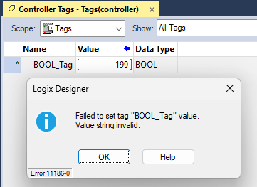
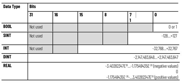
A BOOL, or Boolean, tag can store the values 0 or 1. They can't store letters or other numbers.
A DINT, or Double Integer, tag can store whole numbers between -2,147,483,648 and 2,147,483,647. DINT tags can't store numbers with decimal places or letters.
.png)
A REAL tag can store numbers with decimal places between -3.40282347E38 and 3.40282347E38. REAL tags can't store letters.
.png)
A STRING tag can store letters and numbers. Numbers stored in STRING tags are treated as letters and can't be used in mathematical calculations.
.png)
There are lots of other data types you can use in Studio 5000 Logix Designer. For example, you could use a tag with the data type SINT, INT, or DINT to store a whole number. The difference between these data types is the amount of memory they use: a SINT uses one byte, an INT uses two bytes, and a DINT uses four bytes. Tags that use less memory can store a smaller range of values.
Historically, PLC programmers used tags with smaller data types to save memory in the controller. In Logix 5000 controllers, the smallest amount of space allocated for a tag is four bytes, so SINT, INT, and DINT tags actually take up the same amount of space in the controller.
Attributes
Tags can have additional attributes.
Some attributes, like the Description attribute, let you give a tag more context by adding a description to it.
.png)
Other attributes like External Access and OPC UA Access define if a tag can be accessed by an external device like an HMI or an OPC UA Client.
.png)
The Constant attribute defines whether a tag's value can be changed programmatically or has a constant value that can only be changed in Studio 5000 Logix Designer.
.png)
The Style attribute defines how a tag is displayed in Studio 5000 Logix Designer. You can use this attribute to monitor the individual bits in a DINT tag instead of the decimal number.
.png)
Finally, the Alias Tag and Base Tag attributes let you configure one tag as an alias of another. An alias lets you assign another name to a tag. In this example, DINT_1 is an alias for DINT_2 and will always have the same value as DINT_2. This feature is often used to map Local Tags to Controller Tags.
.png)
Of these attributes, Description and Alias Tag/Base Tag are the ones you'll use most often. The others, External Access, OPC UA Access, and Style, come up in more specific cases, but it's still good to know they exist.
Scope
All tags in a Studio 5000 Logix Designer project have a scope. A tag's scope defines where the tag can be accessed in the project.
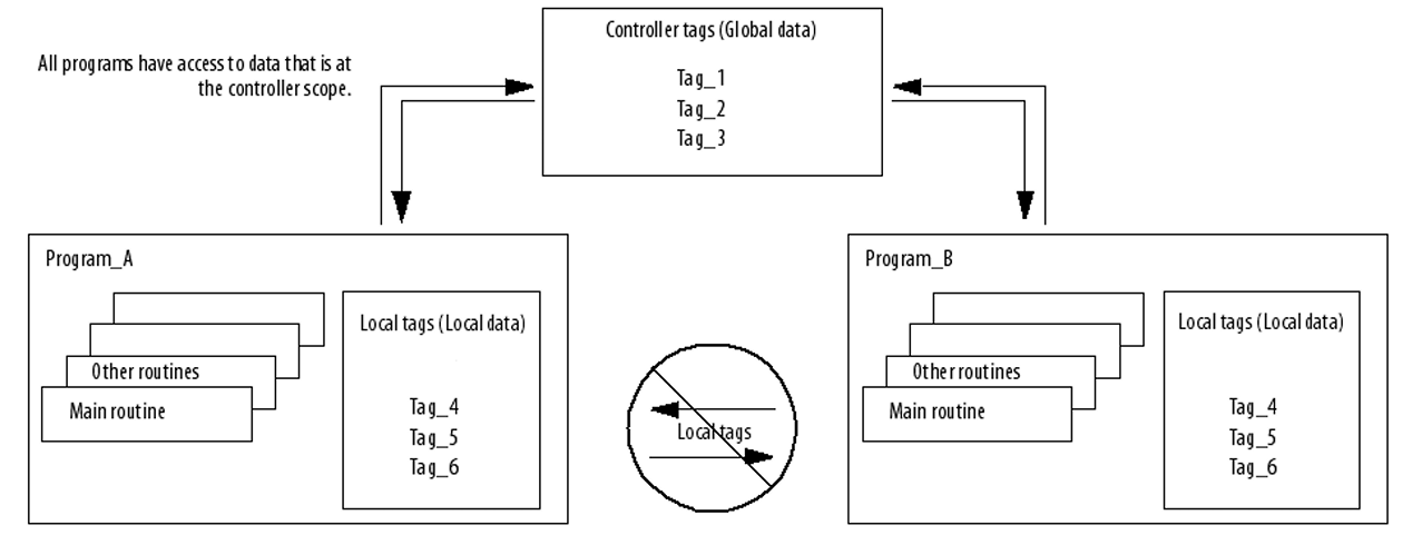
A controller-scoped tag is a global tag that can be accessed anywhere in the project. The names of controller-scoped tags must be unique in a project.
A program-scoped tag is a local tag that can only be accessed in the program where it was declared. Since program-scoped tags are encapsulated in a program, two programs can have a tag with the same name.
Although it's allowed to have a program-scoped tag with the same name as a controller-scoped tag in a project, it's considered bad practice and should be avoided.
Parameters
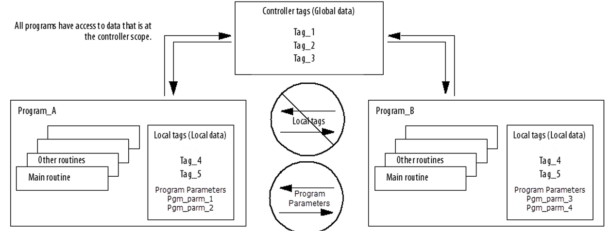
A parameter is a special type of program-scoped tag that can be used to pass data between programs. Historically, this passing of data was done by aliasing local tags to controller tags.
.png)
You can define four different types of parameters in a Studio 5000 Logix Designer project:
An Input Parameter is used to pass data into a program. Input parameters are passed by value, which means the data is passed into the program in a way that's read-only. Input parameter values are updated before the program is executed.
An Output Parameter is used to return data from a program. These parameters are passed by value from the program after the program has executed.
An InOut Parameter is used to exchange data with a program by reference. This means the data can be read and written and can be updated as the program is being executed.
A Public Parameter exposes the data from a program so that it can be read by other programs. Effectively, it turns a program-scoped tag into a controller-scoped tag that's declared at the program level.
Small, single-program projects usually don't need parameters at all, since controller-scoped tags cover most needs. They become much more useful once you're working with larger, multi-program projects.
Wrap Up
In this post, I introduced you to the concepts of tags in Studio 5000 Logix Designer: tags, data types, attributes, scopes, and parameters.
Now that you know how tags work, you might be interested in learning the basics of Ladder Diagram.
Learn PLC Programming in your browser
Learn PLC programming by building projects in your browser - no hardware or software required.
Then €29.97/month · Cancel any time