In this post, I'll explain what a PLC is, walk through the components that make one up, and show you how a PLC actually controls a process.
Let's start with the basics.
What is a PLC?
A PLC, or Programmable Logic Controller, is a specialized industrial computer designed to control automated equipment and processes.
If you're new to industrial automation, you might wonder why we need PLCs at all. Why can't a regular computer control an automated process?
There are three core reasons PLCs are used in industrial automation.
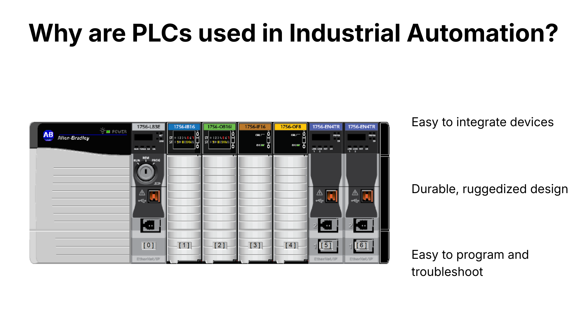
First, they're easy to integrate with other devices. A PLC can communicate with hundreds or even thousands of different sensors and actuators, and connecting a device is often as simple as wiring it directly to the PLC.
Second, PLCs are incredibly durable. They run on a specialized operating system that doesn't need updates or patches, built on solid-state components with no moving parts to wear out. Those components sit inside a ruggedized housing that can survive dirty, dusty environments. Put it all together, and PLCs can run for 10, 15, even 20 years without stopping, which is performance you simply won't get from traditional computers, since those need regular patching and are often obsolete within five years.
Third, PLCs are simple to program and troubleshoot. As you'll see later in this post, they're programmed using high-level, visual programming languages that are easy for technicians, electrical engineers, and process engineers to understand. That matters in manufacturing environments, where the people operating and maintaining equipment are electricians, technicians, and operators, not software engineers.
PLC Architecture
Now that you know why PLCs are used in industrial automation, let's look at the architecture of a typical PLC.
PLCs come in many shapes and sizes, but they're all built from the same core components.
Processor
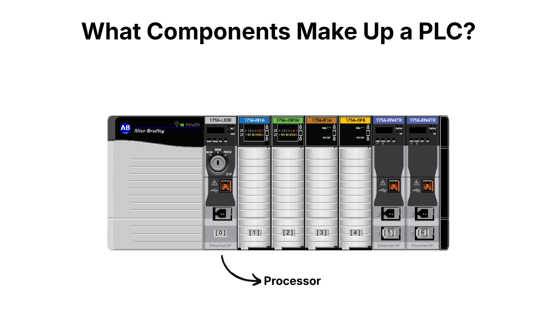
The processor is the brain of the PLC. It's responsible for executing the project downloaded to it, and it contains an interface for downloading that project, non-volatile memory to store it, and a CPU to run it.
I/O Modules
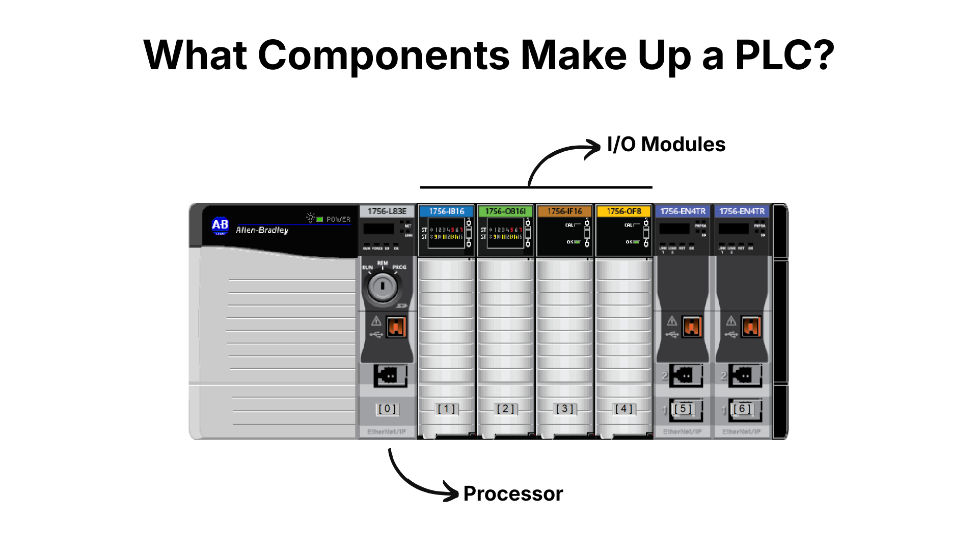
Input and output modules, or I/O modules, let the PLC interact with the physical world. Input modules take electrical signals from devices like pushbuttons and sensors and convert them into digital signals the processor can understand. Output modules do the reverse, taking digital signals from the processor and converting them into electrical signals that actuate devices like lights and motors.
Communication Modules
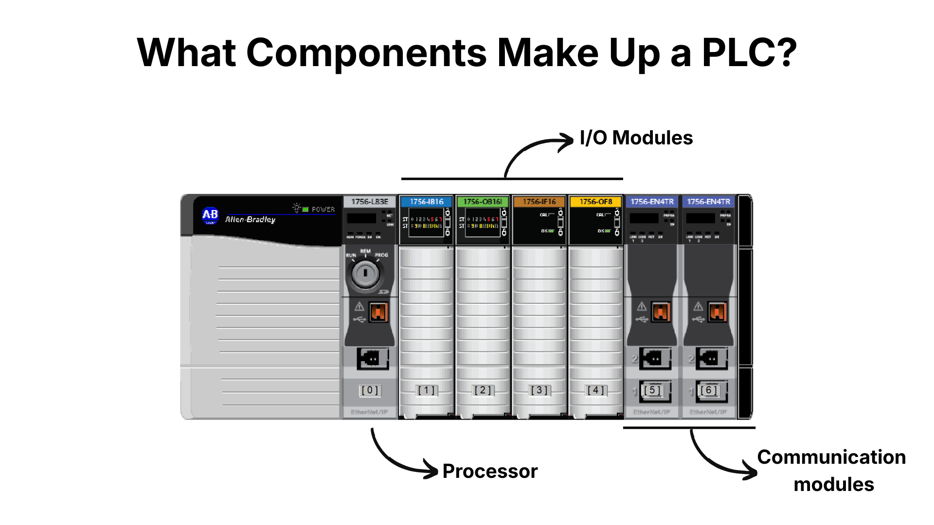
Communication modules let a PLC talk to other devices on industrial networks like EtherNet/IP and PROFINET.
Power Supply
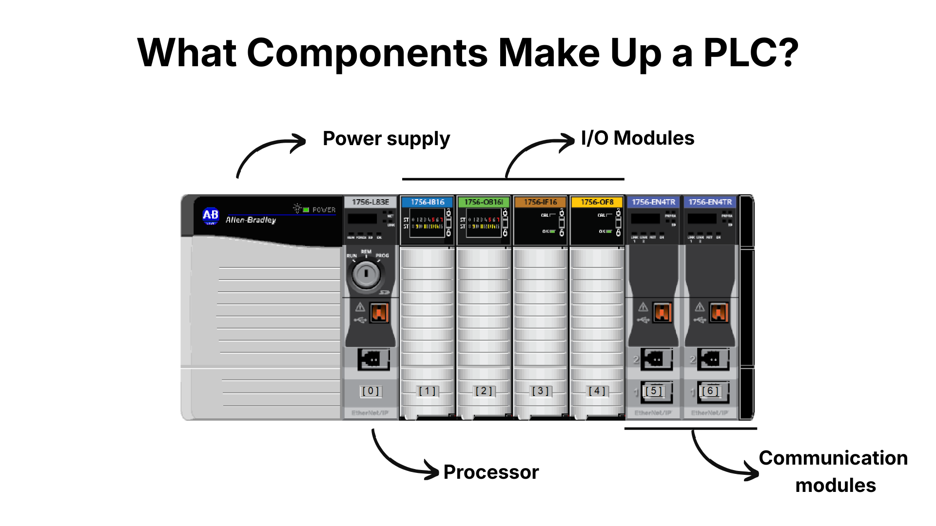
Finally, a power supply provides power to every component in the PLC.
Form Factors
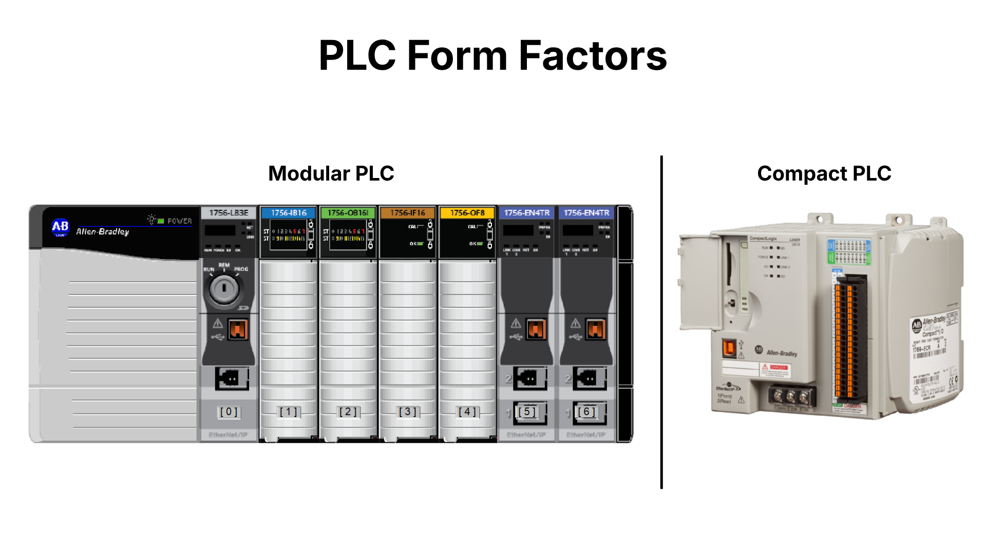
In the example above, each component is its own physical module with its own housing, and these modules install into a chassis to build a PLC system. This is known as a modular PLC system, the form factor used for large, powerful systems. It can be customized to fit a project's needs, and since individual modules can be replaced without touching the rest of the system, it's also easy to maintain.
Other PLCs integrate every component into a single housing. This is called a compact PLC, and it's often used for smaller processes.
How Does a PLC Control a Process?
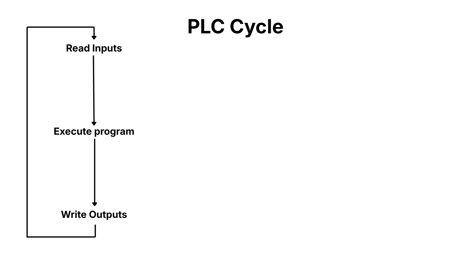
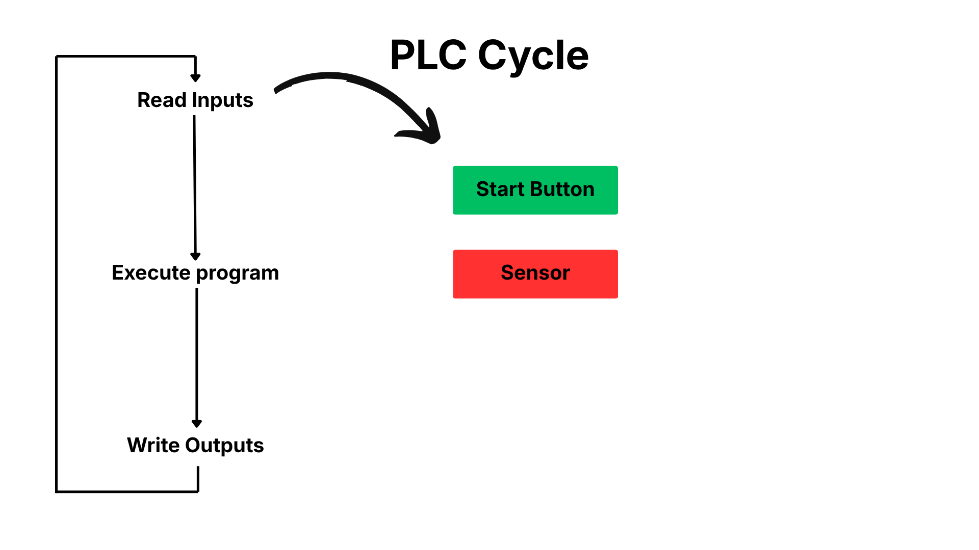
A PLC controls a process by monitoring inputs, executing its program, and controlling outputs. These steps run in an infinite loop, and each pass through that loop is called a scan, or a cycle.
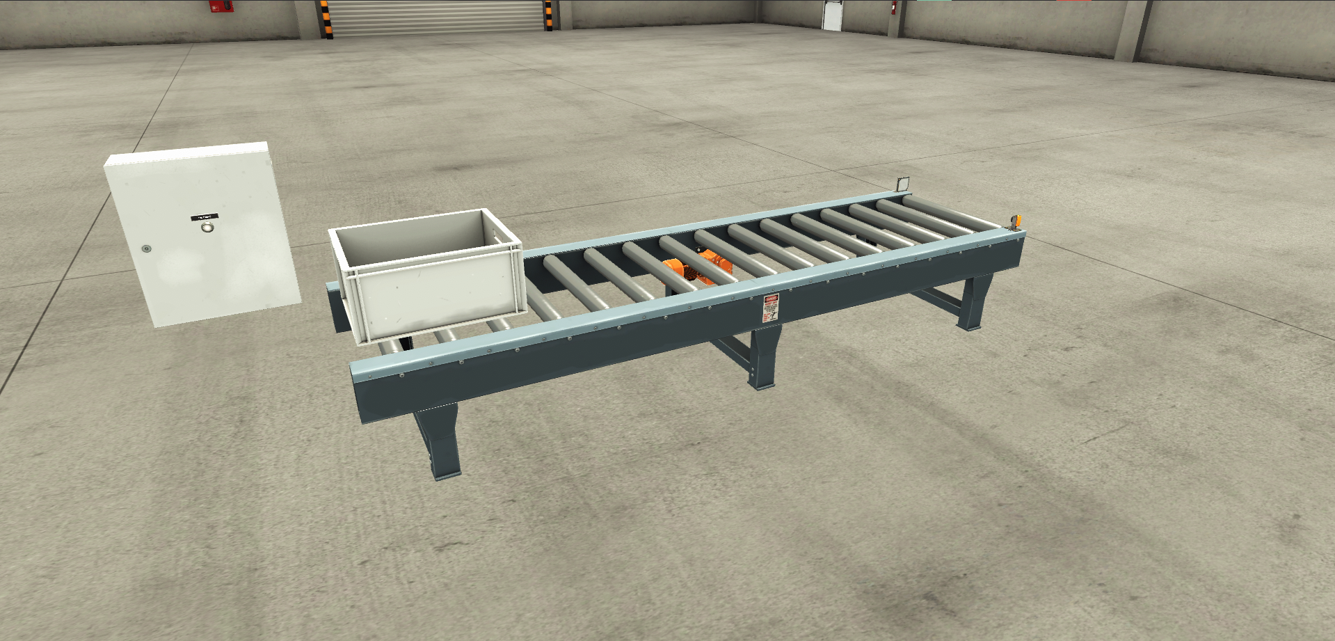
Let's look at a simple example: a PLC controlling a conveyor, where an operator starts the conveyor by pressing the Start button, and it keeps running until the sensor at the end of the conveyor is triggered.
At the start of every scan, the PLC checks the status of its inputs, in this case the Start button and the sensor.
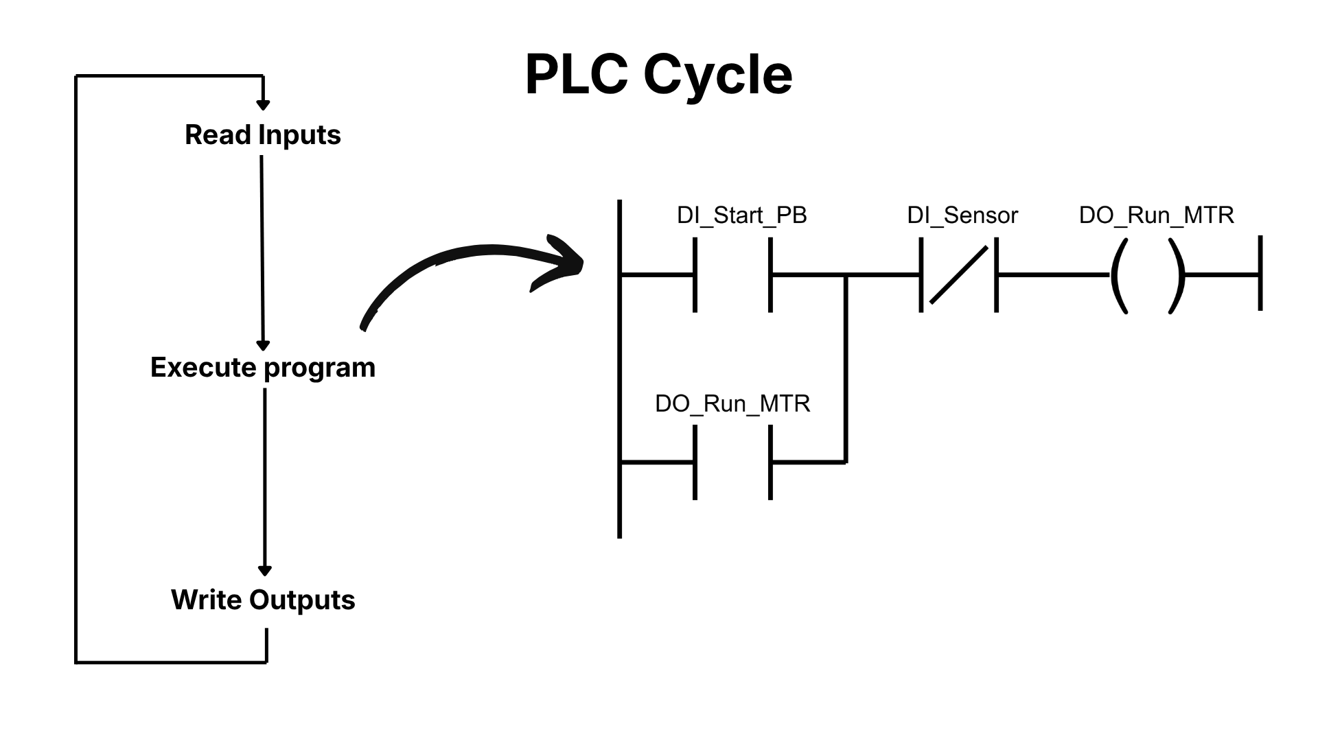
The PLC then executes its program. Simple programs like this one are typically written in Ladder Diagram, a high-level, visual programming language that resembles electrical schematics.
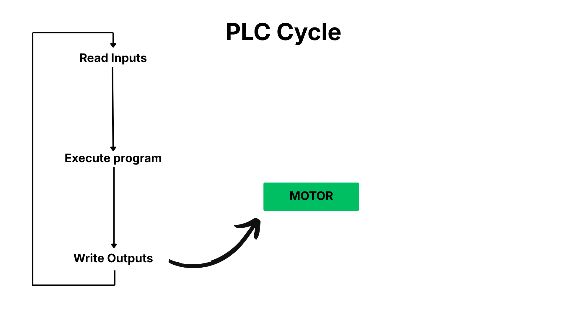
After executing the program, the PLC turns its outputs on or off to control the process.
Wrap Up
In this post, I explained what a PLC is, the components that make one up, and how a PLC controls a process using a simple scan cycle. With that foundation in place, you're ready to start building your first project in Studio 5000 Logix Designer.
If you want to learn more, check out my other post that explains the Ladder Diagram programming language in more detail.
Learn PLC Programming in your browser
Learn PLC programming by building projects in your browser - no hardware or software required.
Then €29.97/month · Cancel any time